ON-LINE MANUAL
Mounting
3.
Where and how to attach the vibrator
3.1.
Linear Piston Vibrators
These
vibrators are used mainly for feeding applications. The most common
feeder forms are channels, chutes and spiral chute feed hoppers. Piston
vibrators are not recommended for emptying bins and hoppers since
they produce impacting energy that moves bin walls back and forth
which can cause oil canning problems as greater force is needed to
make material flow. The impact and the force may cause structural
damage to the bin also. The FP-series are non-impacting.
3.3.1.
Chutes
Chutes
Feeding
materials in chutes
consists mainly of aiding gravity's natural force, since chutes, in
most cases, are mounted with a downward slope. To allow the vibrator
to function properly, the chute should be suspended on laminated iron
springs, fiber springs or rubber elements. The vibration direction
should be horizontal only.
Make
sure the vibrator is mounted rigidly to the chute. If the chute base
is not stiff enough the vibrator should be mounted on a stiffening
channel or U-shaped iron running the full length of the chute.
3.1.2.
Channels and tubes
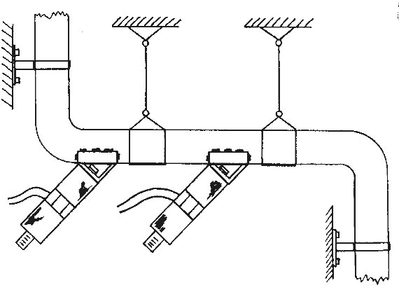
Channel
Channels
or tubes like the one shown above are used to feed fine materials
such as chemical powder, flour, or sugar between silos and production
machines. The advantage is that the material does not come in contact
with anything other than the channel which can be made out of chemical
resistant material. This satisfied regulations regarding cleanliness
and non-contamination in food and pharmaceutical industries.
The
vibrators are mounted with a 45° angle which causes the powder
material to be pushed forward. If necessary additional transversal
rib elements can be fixed in the channel, so even upward slope does
not hinder the feeding.
It
is important to insure that the channel is stiff but not mounted too
rigidly. It is possible to use several piston vibrators in line if
the channel is long, but they have to be of the same type and model
so that they will operate at the same frequency and phase assuming
the channel is stiff. The channel itself can be stiffened by welding
a small channel with heavy wall thickness to the outside of the channel
or tube. Please note that the ends of such stiffener channels must
not be welded for the first 3mm.
3.1.3.
Spiral chute feed hoppers
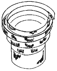
Spiral
chute feed hopper
Spiral
chute feed hoppers are used whenever small bulky parts have to be
feed automatically into machines. They often include a system to position
parts in a certain way when they are fed into the machine.
Normally,
spiral chute feed hoppers are driven by electrical, rotary or electromagnetic
vibrators. Pneumatic piston vibrators are advantageous for saving
space while keeping high vibration power.
The
spiral chute should be mounted on laminated springs or rubber elements.
Two vibrators should be mounted opposite each other to get an imaginary
vertical fulcrum. The exact mounting angle of the vibrators must be
obtained by practical tests, but an angle of 45° to the chute
base line is normally a good value.
3.2.
Rotary Vibrators
Rotary
vibrators produce a sinusoidal vibration. This type of vibrator is
much more efficient in bringing materials into resonance than the
linear vibrators. The frequency of a rotary vibrator can be adjusted
in a wide range by using a pressure or flow regulator.
Rotary
vibrators are used mainly to separate or compact materials. One common
application is emptying bins, silos, and hoppers. The function of
the vibrator in separation applications is to separate clogged material
to free it. Once it is freed it moves downward by the force of gravity.
Rotary
vibrators can be used for feeding materials similarly to linear ones.
Since piston vibrators do not create strong forces, larger rotary
vibrators are commonly used for feeding heavier materials like gravel
in chutes and for screening materials which respond better to sinusoidal
vibrations than impact vibrations.
Linear
vibrators are not effective in compacting concrete. The unidirection
motion will compact when moving forward and separate while moving
backwards. To compact concrete two types of rotary vibrators are used,
namely, internal and external vibrators. Internal vibrators are sometimes
called poker vibrators. That are dipped into concrete, and a needle
containing a rotary mass is driven electrically, pneumatically or
with a flexible shaft by an engine into the concrete. These poker
vibrators are used for building or bridge construction wherever larger
areas are to be compacted. They may also be used in wall, pilon, or
tunnel construction, but external vibrators placed on the outside
moulding form are recommended for these situations.
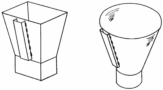
Using
a channel iron
3.2.1.
Mounting on bins and hoppers
Using
a channel iron that is stich welded vertically is the best way to
transfer as much as possible vibration energy into the material inside
the bin. The channel should be placed on the symmetrical axis of the
larger side of a four-cornered bin. Take care that no frame structure
moves closer than half of the length of the channel iron to the channel
iron because it would absorb most of the vibration energy and could
also lead to damage of the frame structure.
The
channel works as stiffener so that the vibrating power is spread over
the full length of the channel. Of course the vibrating power at the
ends of the channel is less than the power near the vibrator. The
vibration waves are pushed away in a 90° angle to the channel’s
length, so the optimal place for the vibrator is on the imaginary
line connecting the channel iron to the center of clogging.
If
the center of clogging is unknown, practical experiences indicated
that a good mounting site is at about 1/3 of the height of the bin
or hopper.
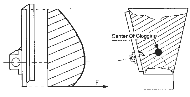
Vibrating
power on a channel / center of clogging
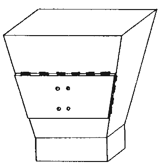
Instead
of a channel iron a plate can be welded to the bin to assure enough
stiffness to spread the vibrating energy throughout the bin or hopper.
Because of their thickness, area and weight a certain amount of vibrating
energy is therefore wasted to vibrate the plate itself.
Using
a plate
3.2.2.
Mounting on screens
Mounting
on a screenAs
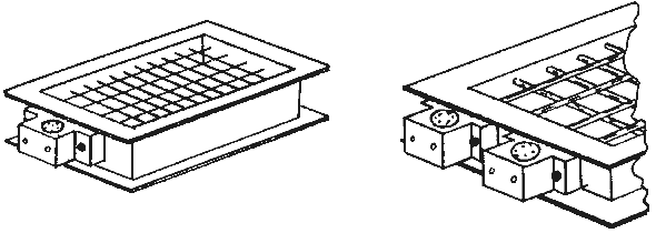
mentioned earlier, screens are very similar to chutes. Screens may
be activated by a vibrator mounted on the smaller edge or in the center.
Often, when screening heavier material like gravel one single vibrator
is not powerful enough. Under such circumstances two units can be
mounted very close to each other. They will immediately synchronize
and double the vibrating power. Take care that the frame is stiff
enough. If it is not, the rigidity can be increased by using channel
(U- or H-type) irons and a vibrator mounted in the center as in the
following figure.
The
screen must be mounted on springs or rubber elements so that the vibration
energy is not absorbed by the screening machinery’s structure. Make
sure the air pressure tube and connection to the vibrator cannot be
mechanically harmed. When mounted outdoors, please refer to paragraph
6.1.4.
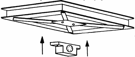
Increasing
the rigidity of a screen (bottom view)
3.2.3.
Mounting on a concrete mold
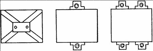
Mounting on a concrete mold (bottom view)
As
with bins, the use of a channel iron or plate is recommended to spread
the vibration energy when mounting on a concrete mold. If the mold
is extremely small (less than 50 by 50 cm / 20 by 20 inches) the vibrator
may be placed in the center under the mold. If it is larger, one of
three configuration is recommended: one vibrator only, two vibrators
mounted opposite each other on the longer sides of the mold, or four
vibrators with two mounted opposite each other on the longer sides
of the mold.
Like
the screens, pneumatic vibrators mounted on molds will synchronize
immediately after they begin to vibrate. The mold should be mounted
on rubber elements or laminated springs, but also fixed in a fairly
rigid position so the mold will not continue to swing or vibrate after
the vibrator’s energy is cut.
3.2.4.
Mounting on a concrete form
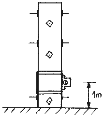
Mounting
on a pilon form
Under
normal circumstances the wooden or iron form plates of concrete pilons
are sufficiently stiff to mount a vibrator since the square area is
relatively small. It is best to place the vibrator relatively close
to the bottom of the pilon, around a height of 1 m. This guarantees
that the lower portion of the pilon will be vibrated correctly. The
upper part can move relatively freely, and the reinforcing steel in
the pilon will transfer the vibration energy upwards. Even for pilons
of up to 4 m in height, one single vibrator is absolutely sufficient.
It can be attached with clamps.
For
longer pilons, instead of using two or more vibrators, the first few
meters should be vibrated as it is poured. Subsquently, every few
meters, the poured concrete should be vibrated separately until the
pilon is completed.
The
time of vibration varies according to the viscosity of the concrete
and the additives used .
Unlike
pilon forms, concrete forms for walls are generally not very stiff.
Hence, the vibrating energy may not be spread very well using only
one vibrator. Instead of using only one vibrator to cover a given
area, several have to be used. They may be smaller accordingly.
The
wall should be vibrated piece by piece (portions of 1 to 2 m in height
at maximum).
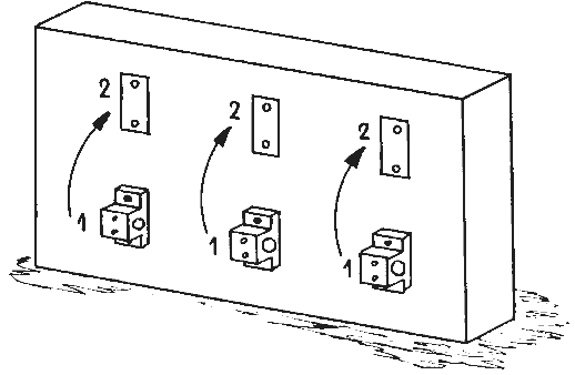
Mounting on a wall form
NEXT TO MOUNTING PART 2

